Techniques BABOK Guide v3, 10.44
State Modelling
In short A state model shows the statuses an entity can have during its life, from creation to deletion, and the events that move it from one status to the next. It turns a vague “status” field into explicit rules that developers can build and testers can check.
Based on: IIBA, BABOK® Guide v3, technique 10.44 “State Modelling”; Watermark Learning, BABOK v3 Study Tables (2016); Yu. A. Maglinets, Analysis of Requirements for Information Systems (in Russian), lecture 5.
On this page
What it is#
The BABOK® Guide uses state modelling to show the states (statuses) that an entity or class passes through over its life cycle, the events or triggers that cause a change, and the transitions themselves. Its elements:
- State: a stable condition in which the entity behaves in a defined way, such as “Awaiting parts”. Name it as a condition, not as an action.
- State transition: a move from one state to another, caused by an event and sometimes allowed only when a condition holds.
- State diagram: the picture. States are rounded boxes, transitions are arrows, a filled dot marks the start, and a ringed dot marks the end.
- State table: the same content as a grid of current state, event, and next state. Tables are better for checking completeness; diagrams are better for discussion.
Maglinets’ lecture notes give the UML label for a transition: Event [guard condition] / action. The event triggers the move, the guard must be true for it to happen, and the action is what the system does on the way. He recommends state diagrams when you need to understand the system as a finite-state machine whose behavior spans more than one use case.
When to use it#
Use it when:
- an entity has a status that decides what people and systems may do with it: orders, applications, tickets, invoices, contracts, repair jobs;
- several use cases or processes change the same entity and you need one consistent view (BABOK task Specify and Model Requirements, 7.1);
- you suspect hidden business rules. A state model is good at surfacing rules, attributes such as dates and reasons, and the activities allowed in each state;
- you need to explain behavior more clearly than prose can.
Use something else when:
- the entity is simple, with two or three obvious states; a sentence will do. The BABOK Guide notes that the technique usually pays off only for complex entities.
- you want to show who does what across a flow of work; use Process Modelling.
- you want the order of messages between participants; use Sequence Diagrams.
Expect some effort. Agreeing on state definitions across stakeholders takes time, and the level of detail can make some of them uncomfortable. Agreeing the terms in the glossary first helps.
How to do it#
- Choose one entity and write a one-line definition of it.
- List the states from documents, screens, reports, and interviews (“What statuses can a job have?”). Merge synonyms; split a state if it hides different behavior.
- Mark the initial and final states.
- List the events: user actions, system events, and time-based events.
- Build the state table. For every state, go through every event and decide: ignore it, reject it, or move to which state, under which guard, with which action.
- Hunt for gaps: unreachable states, dead ends with no way out, and missing cancellation or rollback paths.
- Draw the diagram from the table for review.
- Extract requirements: rules (from guards), attributes (timestamps, reason codes), notifications (from actions), and permissions per state.
- Review with the people who own the entity, then baseline.
- Derive tests: at least one per transition and one per forbidden event in each state.
Example#
The Workshop, a fictional chain of bike-repair workshops, models the life cycle of a repair job:
| Current state | Event [guard] | Next state | Action |
|---|---|---|---|
| (start) | Customer books a slot | Booked | Send confirmation |
| Booked | Customer cancels [more than 24 hours before the slot] | Cancelled | Free the slot |
| Booked | Slot time passes [bike not checked in] | No-show | Alert the front desk |
| Booked | Front desk checks the bike in | Checked in | Print job card |
| Checked in | Mechanic inspects [parts in stock] | In repair | Reserve parts |
| Checked in | Mechanic inspects [parts missing] | Awaiting parts | Create parts order |
| Awaiting parts | Parts delivered | In repair | Alert the mechanic |
| In repair | Mechanic marks complete | Ready for pickup | Notify the customer |
| Ready for pickup | Customer collects and pays | Collected (end) | Close the job |
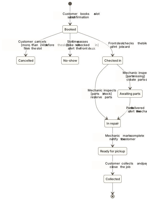
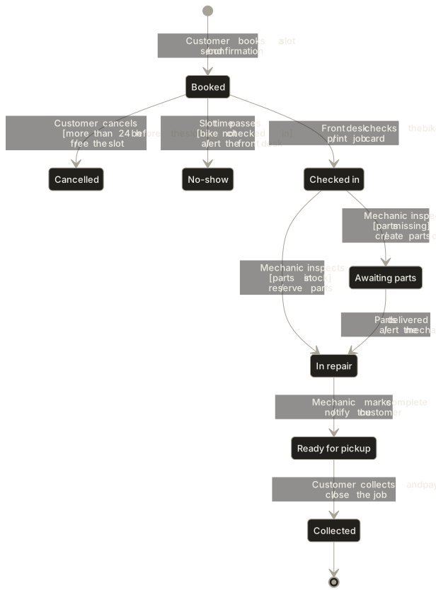
View as text
The diagram shows the same transitions as the state table above, one arrow per row.
Building the table exposed three rules nobody had written down: a late cancellation leaves the job “Booked” so the slot is charged; a job cannot enter “In repair” without reserved parts; and “No-show” needs a reason code for reporting. It also showed a missing path: what happens to a bike left in “Ready for pickup” for weeks. That became an open question for the owner.
Common mistakes#
- States named as activities (“Repair”) → name conditions (“In repair”); activities belong on transitions or in process models.
- Only the happy path → check cancel, reject, timeout, and rollback from every state.
- Two entities in one model (the booking and the invoice) → one entity per model, linked through events.
- Missing or overlapping guards → if two arrows leave a state on the same event, each needs a guard, and the guards must not overlap.
- States without agreed meaning → define each in the glossary with entry and exit conditions.
- Over-modelling → keep the technique for entities whose behavior is genuinely complex.
Template#
Entity: <name> - <one-line definition>
States:
- <state>: <definition / entry condition>
Initial: <state>    Final: <state(s)>

| Current state | Event | Guard [condition] | Next state | Action | Rule ID |
|---|---|---|---|---|---|

Forbidden events:
- <state>: <events that must be rejected, and the message shown>
Open questions: <list>
Checklist#
- Every state has a definition that stakeholders agree on.
- Every state is reachable, and every non-final state has a way out.
- Each state-event pair has been considered, not only the obvious ones.
- Guards on the same event do not overlap.
- Rules, attributes, and notifications found in the model are recorded as requirements.
- Each transition has at least one test.
Sources and further reading#
- IIBA. A Guide to the Business Analysis Body of Knowledge (BABOK® Guide), version 3. International Institute of Business Analysis, 2015, technique 10.44 “State Modelling”.
- Watermark Learning. BABOK v3 Study Tables. 2016. (study aid for the BABOK Guide), technique 10.44.
- Yu. A. Maglinets. Analysis of Requirements for Information Systems, lecture notes (in Russian). Siberian Federal University, 2007, lecture 5 (UML state diagrams, transition labels).